Our Location
No.503 Xingguo Road, Yuhang Economic and
Technological Development Zone, Hangzhou

No.503 Xingguo Road, Yuhang Economic and
Technological Development Zone, Hangzhou

Learn how onsite energy meter calibration works, including portable equipment, CT and VT checks, measurement uncertainty, load conditions, and safety.
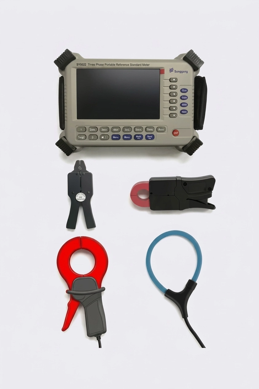
Onsite energy meter calibration verifies an installed meter under real operating conditions without removing it from service. It is used by utilities, industrial facilities, and service teams when downtime, transport, or removal costs make laboratory calibration impractical.
Field calibration is suited to periodic verification, dispute investigation, commissioning checks, incoming inspections, and troubleshooting. It can identify wiring errors, incorrect ratios, phase problems, contact resistance, and measurement drift while the meter remains connected to the load.
Onsite testing does not always replace a controlled laboratory calibration. The decision depends on the required uncertainty, regulatory rules, meter design, and availability of suitable reference equipment.
A portable calibrator usually combines a reference standard meter, voltage and current inputs, clamp or direct connections, pulse measurement, a display, battery power, and data storage. A three-phase onsite calibrator may also include vector diagrams, waveform display, harmonics, and power-quality analysis.
The reference instrument should be traceable, stable over temperature, protected against accidental overvoltage or overcurrent, and practical to connect in confined electrical rooms.
Most field errors are caused by connection or ratio problems rather than the meter itself. Before testing, confirm CT and VT ratios, secondary wiring, test switch condition, phase identification, grounding, and burden. A voltage or current measurement that looks correct in isolation may still be associated with the wrong phase or polarity.
Field conditions introduce uncertainty that is not present in a controlled laboratory. Temperature, electromagnetic interference, long leads, clamp accuracy, unstable load, harmonics, and operator technique can all affect the result.
The test report should separate the calibrator uncertainty from the expanded measurement uncertainty at the meter. A field result that appears outside tolerance should be verified before a meter is removed or adjusted.
Onsite calibration depends on the available load. Low-load or highly variable conditions may make some test points impractical. The operator may need to compare energy over a longer interval, use a suitable load, or verify the meter at the conditions that can be supported safely.
Field calibration involves live electrical equipment. Use suitable PPE, follow lockout and permit procedures, verify the test instrument rating, inspect leads and clamps, and maintain safe clearances. The calibration plan should be approved by the responsible electrical authority.
Not always. It can provide strong field evidence, but the acceptable uncertainty and regulatory requirements determine whether laboratory calibration is still required.
It depends on the number of meters, wiring configuration, load stability, test points, and report requirements. A single meter may take less than an hour, while a large installation may require a detailed schedule.
Include meter identification, site conditions, instrument calibration status, connection details, test points, measured errors, uncertainty, pass/fail conclusions, and recommended actions.
For portable calibration equipment, review our three-phase onsite calibrator or contact us.
If the measured error is outside the expected range, do not adjust the meter immediately. First verify the test setup, phase sequence, CT and VT ratios, clamp direction, lead condition, and actual load. Repeat the measurement at a stable load point and compare it with historical data.
When the error remains consistent, determine whether the cause is the meter, wiring, burden, installation, or reference instrument. Document the evidence and follow the approved correction procedure. In some cases, the meter should be removed for controlled laboratory testing before any adjustment is made.
A complete report supports maintenance planning, regulatory review, and future comparison of meter performance.
